Since we have all grown up around gasoline-powered cars, the general way that they work (i.e. gasoline is burnt in an internal combustion engine, which provides the necessary power to drive the vehicle forward) is fairly well understood. However electric cars are much newer and less mainstream, and so we wanted to take an in-depth look at how exactly electric cars work. In other words, we’ll look at how an electric car moves forward after you’ve put your foot down on the acceleration (‘gas’) pedal.
If you only want a brief explanation of this, please check out the ‘General overview’ section below. But we also provide more detailed explanations in the other sections of this article.
General Overview
The gasoline engines of non-green cars are replaced by an electric motor. Like other electrical devices, it is the motor which provides movement (in the case of a car, via the drive shaft turning the wheels). The motor is powered by rechargeable lithium-ion (electric) batteries. However, it obviously wouldn’t make sense for the motor to be operating on full power at all times. In other words, you wouldn’t want your electric car to go to 80+ mph/130+ kmh the moment you turn your car on, and stay that way until you turn your car off!
Hence a controller (or compact inverter) is used and this ‘sits in the middle’ of the motor and the batteries. As its name would suggest, it controls the battery power that is fed to the electric motor, and it’s how your car will only slowly accelerate when your foot is only slightly touching down on the accelerator pedal:
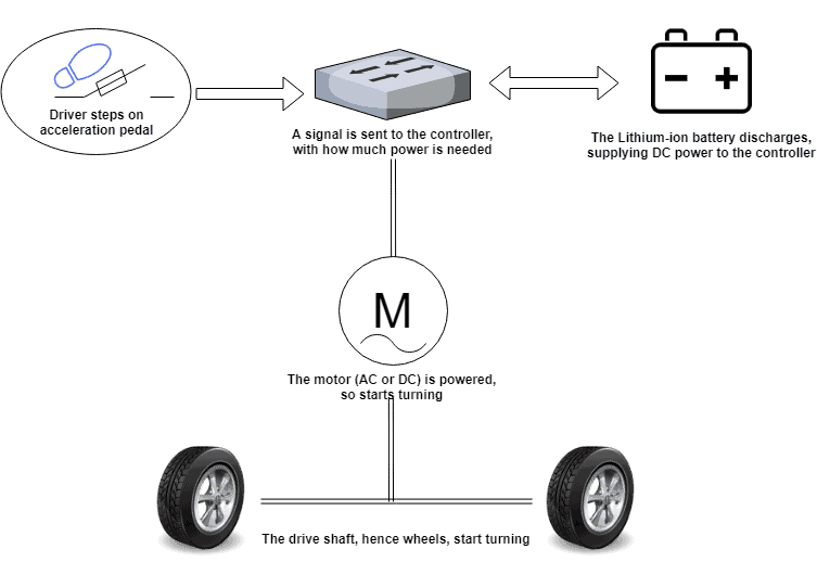
So a brief way of describing how electric cars work is:
- The driver puts their foot down on the accelerator
- A ‘message’ is sent to the controller, which will determine how much power to supply
- This power is supplied from the battery to the motor (via the controller)
- The motor turns the drive shaft accordingly
- This turns the wheels, moving the car forward
And that’s pretty much all there is to it! Unless, of course, you’re interested in knowing the finer details… read on if so!
Accelerator pedal and controller/inverter interaction
To expand on the above, when the driver puts their foot down on the accelerator pedal, this is detected by a pair of variable resistors known as potentiometers. These are used to measure electric potential and are also used in audio equipment, for example when adjusting the volume.
These potentiometers pass a signal to the controller/onboard inverter, essentially telling the controller how much power should be delivered. Naturally, if the driver isn’t touching the pedal, no power should be delivered. And conversely, if the pedal is fully pressed down, full power should be delivered.
As we’ll also explore below, the car’s battery is stored in DC (direct current) whilst the motor is usually AC (alternating current). So the controller/inverter also has the important task of converting from DC to AC power.
The power requirements to move a car at very high speeds obviously mean that the battery and motor will be operating at high voltages, and the controller/inverter therefore has to deal with electric current 15x that found in a typical home air conditioning system. This high level of voltage/current means heat is a big potential problem, and thus cooling is very important in electric cars.
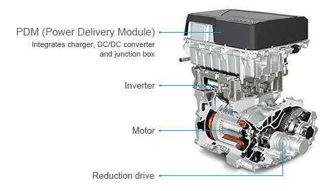
One way that car companies like Nissan have done this is to incrementally reduce the size of the controller/inverter of the years, which also enables easier direct-contact cooling to be applied to the high voltage power module.
So we know that the controller converts DC power to an AC motor (in most cases – sometimes there’s a non-AC motor, as we explore later on) via the signal from the potentiometers. However, this process is not as easy as turning on a tap and having water flow out, either slowly (if the tap is only slightly turned) or quickly (if the tap is fully turned). The very nature of taking digital power and applying it to a physical, analogue system (the motor) means that a process called pulse width modulation (PWM) is required. PWM is used by the controller/inverter to pulse the power accordingly, ensuring that the motor turns at the required level (i.e. instead of operating too slowly or too quickly).
The controller/inverter also handles something known as ‘regenerative braking’, which is where the opposite of the above happens! When the driver brakes, this ‘extra’ power from the motor is collected and supplied back to the battery by the controller.
Finally, the controller/inverter doesn’t just ‘move’ power around. It also houses a range of control circuit technology. These manage other crucial features for EVs such as monitoring the torque and speed of the motor, energy regeneration (back to the battery), failure and anomaly diagnostics, and various safety measures (as set out in an international standard for road vehicle safety, known as ISO 26262).
Electric car battery
The batteries in EVs are lithium-ion batteries:
LIBs are rechargeable and contain lithium based atoms with a non-zero electric charge (ions). A fully charged LIB will have ‘lots’ of negative ions stored, which ‘move’ to the positive electrode when they’re discharged (used). Then they move back when charged. In other words, a lithium-ion based battery simply involves atoms moving from ‘charged’ to ‘used’ positions within the battery. Unlike other forms of batteries, LIBs are quite efficient at being charged and discharged without becoming too inefficient too quickly.
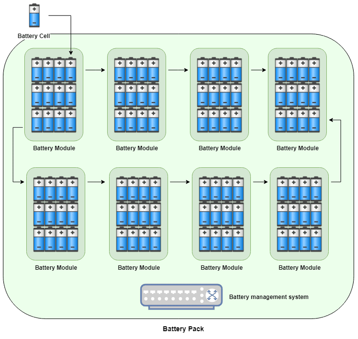
Unlike mobile phone batteries which don’t need to supply much power (in relative terms), car batteries are comprised of multiple cells and modules to achieve the power needed. Think of this as multiple batteries being ‘stuck’ together, and the overall ‘battery’ (cells and modules) make up the pack.
A battery cell is the basic lithium-ion battery unit, similar to a standard household battery. This cell can ‘give out’ electrical power by discharging, then ‘receive’ power by charging. At the micro-level, each cell is comprised of a cathode (+ positive), anode (- negative), separator and electrolyte – and packaged in a metal case.
A battery module is a group of multiple cells, assembled in a frame to protect from heat and vibrations. Each battery module will have positive and negative power switches to regulate and control the power flow.
A battery pack is a group of multiple modules, and is the final ‘battery’ which we would see in an electric car. In addition to the modules, it also contains various control and protection systems (such as a BMS), and also a cooling system.
The way that different car manufacturers configure their battery varies, however. The BMW i3 has a total of 96 battery cells across 8 modules: in other words, 12 cells per module, and 8 modules per pack, leading to a 33 kWh battery:
The Tesla Model 3 is completely different, though, in that it has 2,976 high density cells across 4 separate modules, forming the 50 kWh battery pack.
Electric car batteries run at high voltages as well, for example the i3’s battery runs at 360 volts and the Model S runs at 375 volts. Remember that most American homes have a 120V nominal voltage, and UK homes are supplied at 230V. So electric cars are have a higher running voltage than the domestic supply to homes!
Each individual cell are connected to the module, and each individual module is connected to the pack, in a way that it broadly functions as a single battery. So when the controller decides that it needs power, the circuit will be closed and thus the (group of) battery cells will start discharging – supplying power to the controller. As we seen above, after some conversion and PWM, this power goes to the car motor…
Electric car motor and drive shaft
In general, electric cars use one of two types of motor:
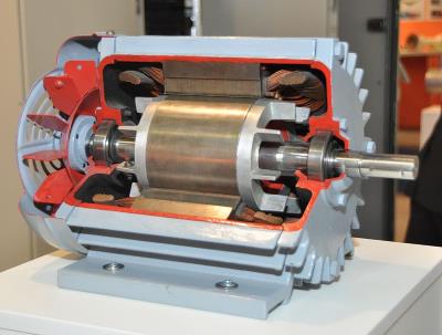
- Brushed DC Motor: this motor runs off DC power and it has 3 main components: the stator, rotor and brush system. The stator contains a permanent magnet system which ultimately provides the turning of the motor’s output shaft. The brushes are made out of electrically conductible material such as graphite, and (when charged) they supply the current through the motor’s commutator bars into the winding.
- AC Motor: this has just two main components, the outside stator (which has coils supplied with AC, triggering the rotational magnetic system) and inside rotor (which produces a secondary magnetic field). The inside rotor attaches to the drive shaft.
Traditionally, DC motors have been more commonplace (in industry and thus in early EV cars), however AC motors are now more popular – in large part due to being easier to produce, install and they don’t have brushes which can wear out. DC motors tend to run at lower voltages (96-192 volts) than AC motors, which are usually 240 volts.
Both DC and AC motors are controlled via magnetic systems, and these magnetic effects are generated when electrical current is supplied to it. So following on from the earlier sections, the driver will put their foot down on the accelerator, meaning that the potentiometers will supply information to the controller about how much current is needed. This is ‘taken’ from the battery pack, and after converting from DC battery power to AC power (for an AC motor, that is) the controller supplies this to the motor. The motor’s magnetic fields function such that the motor’s output shaft – aka the drive shaft of the vehicle – turn as expected, and so the wheels turn.
One future development to this process, however, is the concept of an in-wheel motor – which Nissan’s future technology page sums up well. Basically the standard model of the motor taking the place of a combustion engine was mainly due to simplicity, since the vast majority of parts (and designs) in the market were gasoline-vehicle centric. But with an electrical based system, there’s less limitations and thus more scope for specific improvements. With an in-wheel motor, instead of having a single motor which drives the drive shaft, an EV would instead have two motors which are ‘attached’ to the wheel. This development will hopefully hit mainstream car tech in a few years, and it’ll lead to better handling and responsiveness when driving an EV.
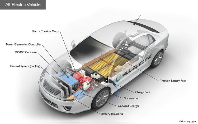
Overall EV diagram
Phew! That’s pretty much ‘all’ there is to the process. A good analogy is that whilst gasoline powered cars are plumbing systems (i.e. moving liquids around, sometimes burning that in a ‘boiler’ type system), electric cars are – you guessed it – like electrical systems! We hope you enjoyed this article, and the below diagram (thanks to afdc.energy.gov) shows various parts of what was discussed: